What you can do
PKR Core generates a voxel microstructure from a reproducible recipe. Same recipe and same seed, same structure — which is what makes any later comparison meaningful.
- Six generators: particle packing, fiber packing, platelet packing, foam-like, layered, and woven fiber.
- A structure is a voxel grid where each voxel holds a material id; 0 is pore.
- The same structure feeds the 3D view, the cross-section inspector, the property analyses, and every export format.
Step 1: set the packing parameters
Open the tool and switch the side panel to Generate. The panel carries the parameters you change most often: generator, grid size, voxel size, seed, volume fraction, and filler radius. Anything beyond that — binder placement, overlap, multiple filler configs — lives behind Open Parameter settings.
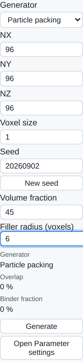
The run below uses a 96³ grid at 1 µm per voxel, seed 20260902, 45 % sphere filler at radius 6 voxels, 15 % overlap, and an 8 % binder placed as a one-voxel surface shell.
Step 2: look at what came out
The 3D view gives you the outside. For what is happening inside, the cross-section inspector cuts a plane through the structure and colours it by material id, which is usually the faster way to spot a packing that has gone wrong.

This is where a recipe either looks like what you intended or does not. Overlapping particles, a binder shell that never formed, a volume fraction that quietly failed to reach target — all of it is visible in one plane.
Step 3: run a property
With a structure loaded, the Analysis menu exposes the property solvers. Each one takes the current structure, the material properties you assigned, and a direction, and each offers more than one method so you can trade accuracy against time.
| Property | Methods available |
|---|---|
| Conductivity | simple, 3d, graph-network |
| Diffusion | effective-medium, graph-network |
| Permeability | pore-network, graph-network |
| Elasticity | voxel-spring-network |
| Invasion percolation | graph-network |
| CO2 adsorption | graph-network |
Metrics that do not need a solver — porosity, specific surface area, tortuosity, pore size distribution — are computed alongside the structure itself. For the run above, the voxel counts came out at 45.01 % filler, 8.00 % binder, and 46.99 % pore against a 45 % / 8 % target.
Where to go next
- Change one parameter and rebuild — or, if you want the whole curve, hand the recipe to a Parametric Study.
- Export the structure as .leS, OBJ, STL, VTK, or an Abaqus / Fluent mesh for another tool.
- Import a measured stack instead of generating one; everything downstream is identical.